В гугле забанили?Сообщение от alex3


В гугле забанили?
Подчиненный перед лицом начальствующим должен иметь вид лихой и придурковатый, дабы разумением своим не смущать начальство.
Указ Петра I от 09.12.1709:
техас удолил файлы - и д-классу таки на выходе оно нужнее, ибо проблемное всё даже в топе TPA32х
Класс Д. Оно всё равно не УПТ. Портить там уже нечего. Ставьте любые.

Да ну?!
https://www.ti.com/lit/an/slaa788a/slaa788a.pdf
"Замполит, чайку?"(с)"Охота за Красным Октябрем".
"Да мне-то что, меняйтесь!"(с)анек.
<-- http://altor1.narod.ru --> Вопросы - в личку, е-мейл, скайп.
Access Denied
You don*t have permission to access "http://www.ti.com/lit/an/slaa788a/slaa788a.pdf" on this server.
Pioneer MU-70 - Technics EPA-A501M/B500 - Goldring G1042/G1022GX - Marantz SC-11/SM-11 - TQWTmk2 by Troels G.
Подчиненный перед лицом начальствующим должен иметь вид лихой и придурковатый, дабы разумением своим не смущать начальство.
Указ Петра I от 09.12.1709:
Ну это не значит, что "техас удолил", это другое(С).
"Замполит, чайку?"(с)"Охота за Красным Октябрем".
"Да мне-то что, меняйтесь!"(с)анек.
<-- http://altor1.narod.ru --> Вопросы - в личку, е-мейл, скайп.
Alex, признайся уж честно - ты еврей или америкашка, по паспорту ))
бремя доказательства лежит на утверждающем - а значит ссылку дает озвучивший документ
народ пишет что разница очень значительная и очень слышно, особо после выхода с микрухи - ну, за что боролись, никогда такого не напоролись, и вот оно опять...
но пишутъ де GaN-транзисторы если придут то окончательно пропадут диофильские катушки пленки с кулак (спойлер нет)))
Последний раз редактировалось Konkere; 13.10.2023 в 13:41. Причина: Нарушение правил форума (дополнение от 01. 08. 2009)
Меандр отвратительный, даже на 1 кГц. Такого ужаса я ещё нигде не видел. Фу. Я-то думал мы тут "бабушкино радио" обсуждаем. А оказывается всё ещё хуже. Не важно что там народ говорит, по даташиту всё уже понятно.
там больше влияет дроссель на выходе, собственно он дает максимум искажений, на входе конденсаторы уже прицепом в ООС попали. На ма12070 частоту подняли до 1,2ГГц и фильтр на выходе почти не нужен оказался, стоит бусина на 5мкГ, вот там конденсаторы вне ООС и ничего, вполне себе приличное качество. Я туда или PPS от панасоника ставлю, или силмик2
Подчиненный перед лицом начальствующим должен иметь вид лихой и придурковатый, дабы разумением своим не смущать начальство.
Указ Петра I от 09.12.1709:
Второго у меня нет, а первый я вообще не знаю что это такое.
Это даже не национальность, а тем более паспорт.
На который указывает первая-же ссылка в гуггле...
Последний раз редактировалось Alex; 13.10.2023 в 17:12.
"Замполит, чайку?"(с)"Охота за Красным Октябрем".
"Да мне-то что, меняйтесь!"(с)анек.
<-- http://altor1.narod.ru --> Вопросы - в личку, е-мейл, скайп.

ГГц?!
WBR, Michael.
Цель расчетов - понимание, а не числа (с) Хемминг.

ТС ошибься - MГц.
Кручина твоя — не причина, а только ступень для тебя. Ю. Визбор
Слабо?подумаешь в 1000 раз ашипся
Подчиненный перед лицом начальствующим должен иметь вид лихой и придурковатый, дабы разумением своим не смущать начальство.
Указ Петра I от 09.12.1709:
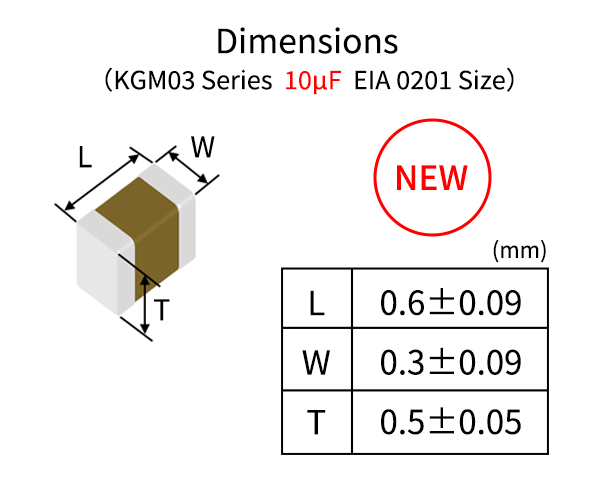
Kyocera*s KGM03 series, measuring just 0.6mm x 0.3mm, is one of the most widely used MLCCs in smartphones and wearable devices. With greater capacitance from an MLCC this small, designers will be able to meet system requirements using fewer components and less space.
Compared to Kyocera*s previous components, the new 0201 MLCCs deliver an approximately twofold increase in capacitance, the highest* in the industry for a 0201 case size
---------- Capacitor distortion ----------
4 types of capacitors are investigated - aluminum electrolytic (unipolar and bipolar), tantalum electrolytic, high K ceramic X7R and MKT polyester film. 3 different test circuits are used. As a signal source serves Topping D10s DAC, for measurements E1DA Cosmos ADC is used.
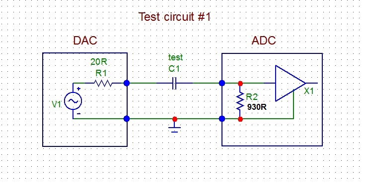
Test circuit #1
Output from the DAC is connected to the capacitor under test C1 which is connected to the input of the ADC. Input impedance of the ADC is 930 ohm, by measurement.
Capacitors under test:
10uF/100V aluminum electrolytic capacitor
4.7uF/6.3V tantalum electrolytic capacitor
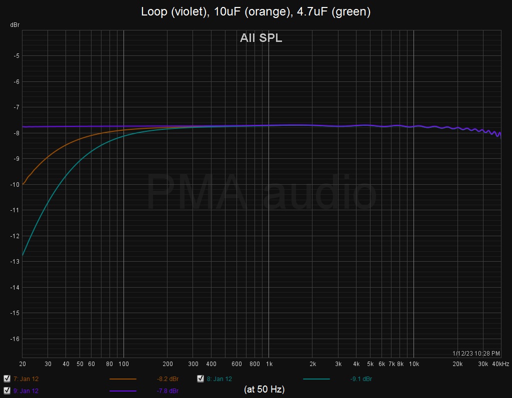
As a most revealing test, THD vs. frequency distortion measurement was used, with a sine sweep from 20Hz to 22kHz and measuring bandwidth 45kHz. Measurements were made at 1.75Vrms DAC output voltage. Fig.2 shows frequency response with both capacitors in the measuring loop and for the direct DAC-ADC loop without tested capacitors. Fig.3 shows THD vs. frequency plots for both capacitors and for the DAC-ADC loop.
Fig.2. Frequency response of the DAC-ADC loop, loop with 10uF capacitor, loop with 4.7uF capacitor
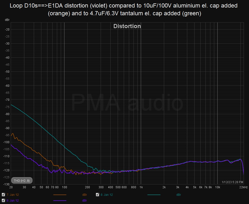
Fig.3. THD vs. frequency of the DAC-ADC loop, loop with 10uF capacitor, loop with 4.7uF capacitor
We can see that both electrolytic capacitors add low frequency (LF) distortion, which starts to rise below 300Hz with the 10uF aluminum capacitor and below 150Hz with the 4.7uF tantalum capacitor. But we can also see the rise of LF distortion below 70Hz for the DAC-ADC direct loop, which is most probably a result of input ADC electrolytic capacitor distortion, because the input impedance of the 1st opamp in the ADC is quite low.
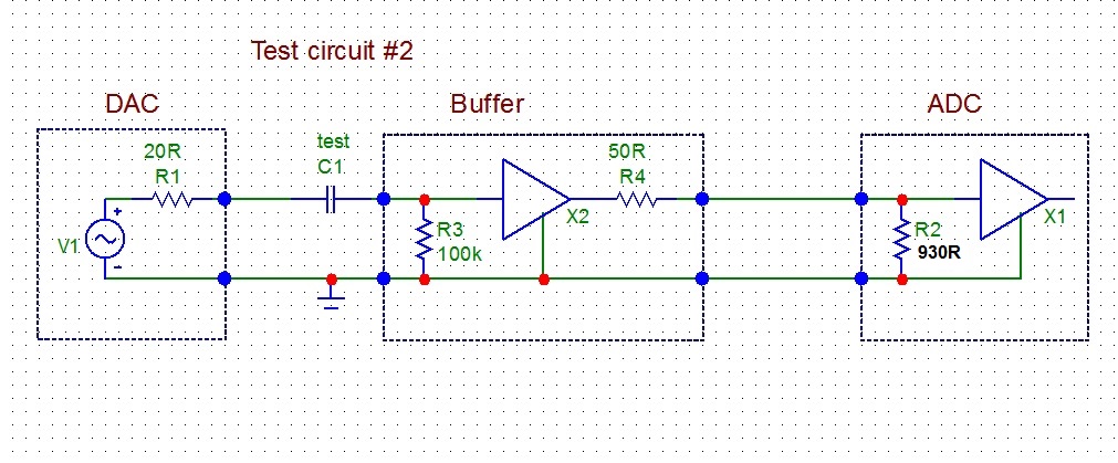
In the previous test (#1) the capacitors under test were loaded by quite low input impedance of the ADC, 930 ohm. Let*s allow much less difficult load of the same capacitors. It will be 100 kohm instead of previous 930 ohm. For this reason, Audio Buffer with 100 kohm input impedance, 50 ohm ouput impedance and gain = +1 is inserted into the measuring loop as a capacitor load. Please see Fig.4.
Again, THD vs. frequency was measured and the capacitors under test were:
10uF/100V aluminum electrolytic capacitor
4.7uF/6.3V tantalum electrolytic capacitor
100nF/63V ceramic X7R capacitor
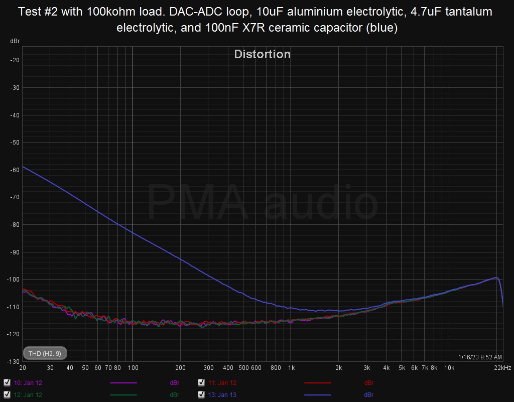
The test voltage was 1.7Vrms. The result is shown in Fig.5.
Fig.5. THD vs. frequency with 100kohm load
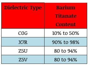
We can see now that with the light load of 100kohm, the distortion plots of the loopback and 10uF and 4.7uF capacitors do overlap. The only exception is distortion plot with the 100nF X7R capacitor, which shows high LF distortion, starting as soon as below 1kHz, though the CR filter -3dB corner of the high-pass (100nF+100kohm) filter is at 15.9Hz. Please avoid high K ceramic capacitors (like X7R) in the signal path!
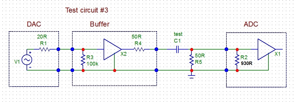
The last test compares distortion of a bipolar electrolytic capacitor composed of anti-series connection of two 47uF/35V aluminum electrolytic capacitors (resulting in 23.5uF capacitance) with distortion of the polyester foil MKT capacitor 22uF/250V=. Capacitors under test are now loaded with 50 ohm resistor and driven from 50 ohm output impedance of the Audio Buffer (Fig.6). Low frequency -3dB corner of the high pass filter 22uF+50ohm is now 72Hz/-3dB.
Capacitors under test:
47uF/35V + 47uF/35V bipolar aluminum electrolytic capacitor
22uF/250V= polyester film MKT capacitor
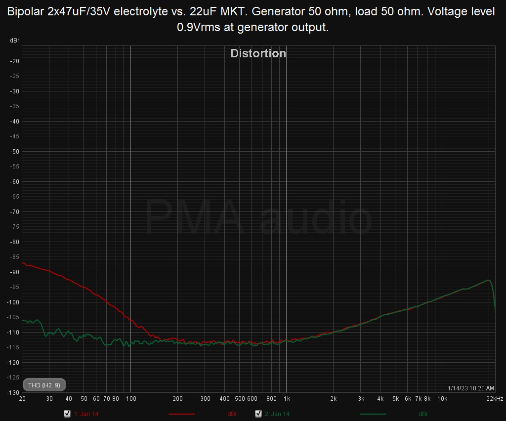
In Fig.7 we can see THD vs. frequency distortion plots for both capacitors, at 0.9Vrms from Audio Buffer output.
Fig.7. 22uF MKT capacitor distortion (green) vs. bipolar 47uF+47uF electrolytic capacitor distortion (red)
The MKT foil capacitor brings no LF distortion, however the bipolar electrolytic capacitor adds LF distortion below 150Hz.
Хорошие измерения.
Но как бы, ничего нового.
"Замполит, чайку?"(с)"Охота за Красным Октябрем".
"Да мне-то что, меняйтесь!"(с)анек.
<-- http://altor1.narod.ru --> Вопросы - в личку, е-мейл, скайп.
EDDiE,Спасибо, наглядно. А нет ли в природе измерений конденсаторов при амплитуде сигнала миливольт так 1...10, или ещё меньше? Там могут выплыть некоторые эффекты, которых на 1В и не видать совсем.
«Не торопитесь соглашаться или опровергать. Не так уж важно, что утверждает или отрицает автор. Важно то, что он направляет Ваше внимание по определенному руслу». Павел Сергеевич Таранов.
Есть, но, там тоже ничего нового.
Signal distortion from high-K ceramic capacitors by John Caldwell, Texas Instruments
The filter circuit shown in Figure 1 incorporates passive component values, which allow capacitors C1 and C2 to be replaced with MLCCs of varying dielectric types and package sizes, allowing the direct comparison of measurements between different capacitor types. All of the capacitors used in this testing had voltage ratings of 50V.
THD+N measurements were made on the filter circuit for a 1 Vrms signal over the frequency range of 20 Hz to 20 kHz with a measurement bandwidth of 500 kHz. Figure 2 shows the measured THD+N performance of the circuit in dB relative to 1 Vrms for different capacitor types. MLCCs of the C0G dielectric type in 1206 packages deliver exceptional performance: the measured THD+N in the filter’s pass-band is at the noise floor of the measurement system. C0G capacitors in 0805 packages were also tested and provide the exact same level of performance
The combined capacitor voltages and measured THD+N of the low-pass filter circuit
https://www.edn.com/signal-distortio...DcyNC40OS4wLjA.
А взяли бы не SK а MFB, было бы еще лучше.
"Замполит, чайку?"(с)"Охота за Красным Октябрем".
"Да мне-то что, меняйтесь!"(с)анек.
<-- http://altor1.narod.ru --> Вопросы - в личку, е-мейл, скайп.
More about understanding the distortion mechanism of high-K MLCCs
The underlying mechanism causing this distortion is the voltage coefficient of capacitance (VCC) of the capacitor. The term VCC is used to describe the change in the value of a capacitor with respect to the magnitude of the applied voltage. Power supply designers are well aware of this behavior as it can directly affect the output ripple or stability of their system, but VCC is often ignored in small-signal circuitry. In order to understand why the capacitance varies with applied voltage and how the VCC varies with other capacitor parameters, it is necessary to first look at a capacitor’s basic structure.
The electric field intensities in Figure 2 may seem unlikely to occur in small signal circuits. However, in the pursuit of higher volumetric efficiencies, capacitor manufacturers are able to produce ceramic capacitors with dielectric thicknesses below 5 micrometers, creating surprisingly high electric field intensities
Using equation 2, we can see that applying 1V to a capacitor with a 5 μm dielectric thickness results in an electric field intensity of 200,000 V/m
SPICE netlist for a nonlinear capacitor
Simulation schematic of a Sallen-Key 1 kHz lowpass filter with X7R capacitors shown as CX1 and CX2
https://www.edn.com/more-about-under...-high-k-mlccs/
---------- Вместе с тем ----------
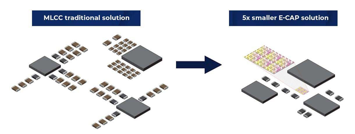
The New Silicon Capacitor Revolution
Compared to the ubiquitous multilayer ceramic capacitors (MLCC), E-CAP offers vastly improved electrical and mechanical performance:
5x greater density
No AC/DC, temperature or aging derating
Ultra-low 15pH ESL
Ultra-wide bandwidth
50μm or lower thickness capable
No audible noise susceptibility
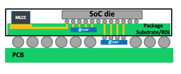
The superior E-CAP stability allows to reduce the nominal capacitance needed to guarantee the effective capacitance required by the system. And with their compact form, thinness and improved electrical performance, E-CAP products are perfectly suited for high-frequency/high-speed data intensive power-hungry applications where power and signal integrity is critical.
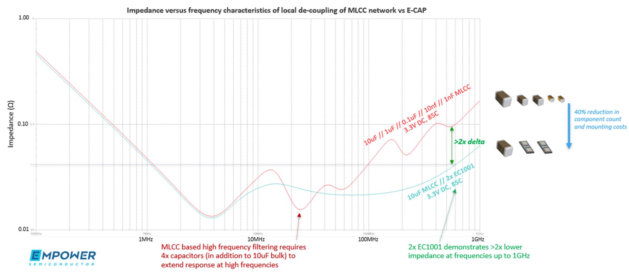
Bypass capacitors for high frequency switching regulators: breaking the 5MHz barrier
https://www.empowersemi.com/wp-conte...-Letter_d1.pdf
https://www.empowersemi.com/an-intro...on-capacitors/
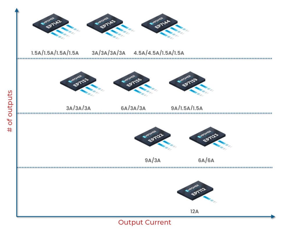
The EP71XX Series is the industry’s highest density IVR, integrating four voltage rails in a miniature IC offering industry-leading performance and extensive fault protection without external discrete components
https://www.empowersemi.com/3-3v-int...egulators-ivr/

 Ответить с цитированием


Социальные закладки