Figure 5: Grounded grid triode output curves (see text).
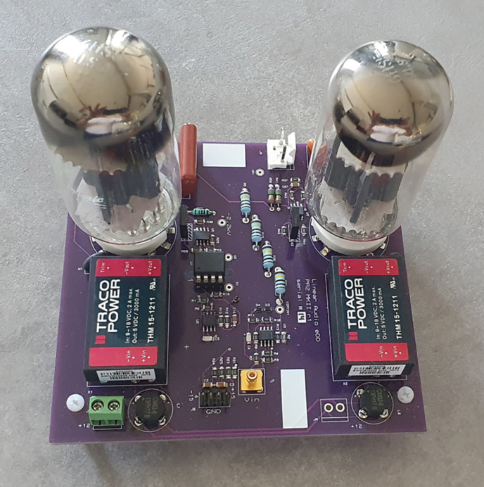
Photo 2: The high-voltage amp PCB, top side.
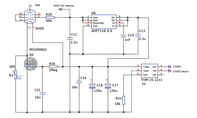
Figure 6: The tube floating bias and heater supplies.
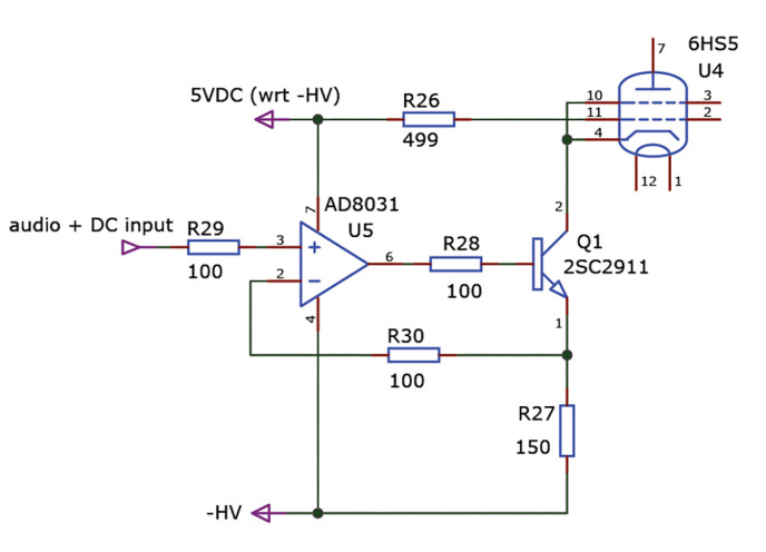
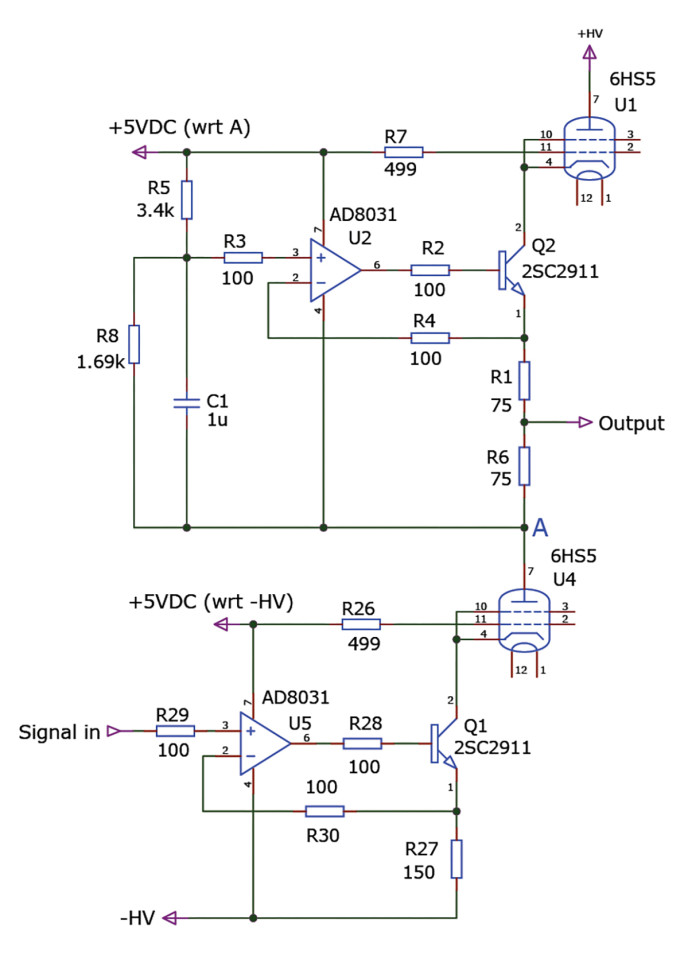
Figure 7: Voltage to current converter cathode driven circuit.
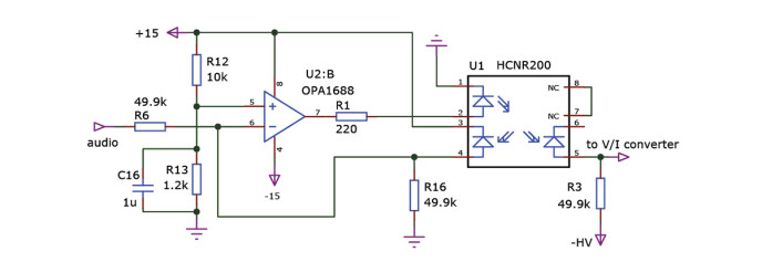
Figure 8: Optical isolator audio translation circuit.
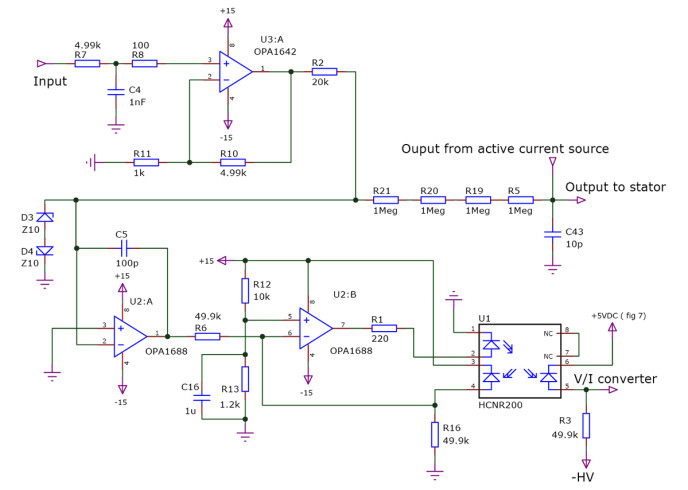
Figure 9: Preamp, feedback, and isolation circuit.
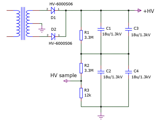
Figure 10: High voltage power supply (pos polarity shown).
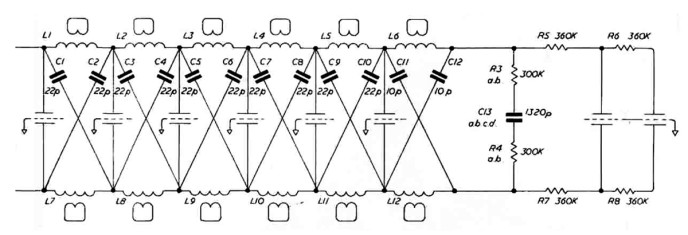
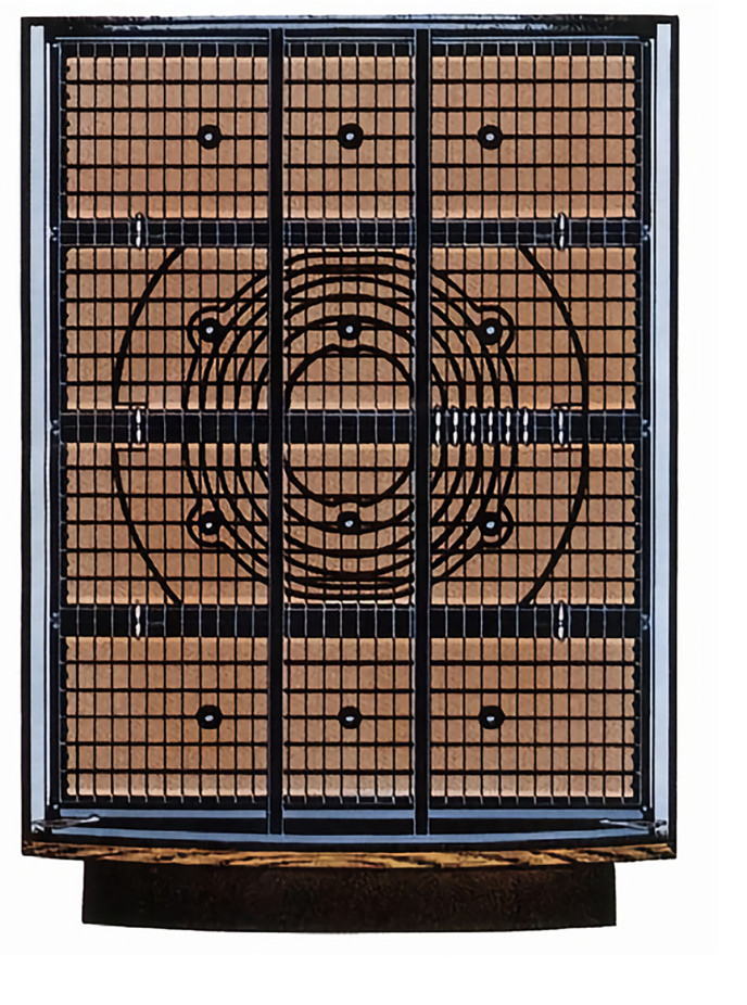
Figure 1: ESL63 transmission line circuit (see text).
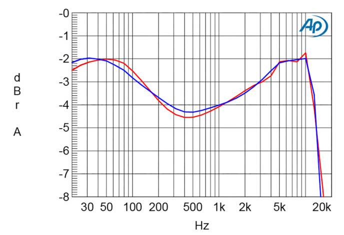
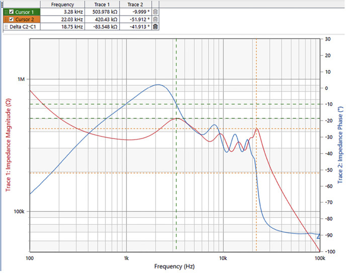
Figure 12: Frequency response at the stators, from the step-up transformer (red) and equalized response from the direct drive amp (blue).
 https://audioxpress.com/article/you-...tatic-speakers
[свернуть]


 Ответить с цитированием
Социальные закладки